A common mistake contractors make in Liverpool is assuming diaphragm walls behave the same as in stiff London Clay. The underlying geology here — deep alluvial deposits of the Mersey basin — presents very different challenges. We’ve seen designs based on generic parameters fail during excavation because they didn’t account for the low shear strength and high pore pressures typical of the Liverpool Formation sands and laminated silts. That’s why our diaphragm wall design process starts with site-specific data: we correlate on-site SPT results with triaxial testing from our UKAS-accredited lab, then run numerical models using Mohr-Coulomb parameters calibrated to local conditions. Before committing to a wall thickness, we also recommend a stability analysis of the temporary trench to evaluate collapse risk under bentonite support, and a permeability test in the field to estimate flow rates through the alluvial strata.
In Liverpool, the water table and boulder-rich till dictate wall design — you can’t rely on London parameters or generic charts.
Process overview
The Mersey Valley’s water table sits only 1.5 to 3 metres below ground across most of Liverpool, and the underlying glacial till contains boulders up to 0.5 m in diameter. These two factors dominate diaphragm wall design in the city. We follow Eurocode 7 (BS EN 1997-1:2004) with partial factors set to UK National Annex values, and we check serviceability limits against lateral wall movements of 0.5% of excavation depth — a threshold we’ve validated against monitoring data from Albert Dock and Liverpool ONE projects. Our design procedure includes:
Hydraulic fracture verification for bentonite support pressure in pervious sands
Uplift check considering the full hydrostatic head at base of wall
Structural section design with crack width limits per BS EN 1992-3 for water-retaining structures
Equivalent fluid pressure diagrams for temporary propping sequences
We cross-check every parameter with our in-house database of Liverpool soil profiles, which covers over 120 boreholes logged from the Wirral to the city centre.
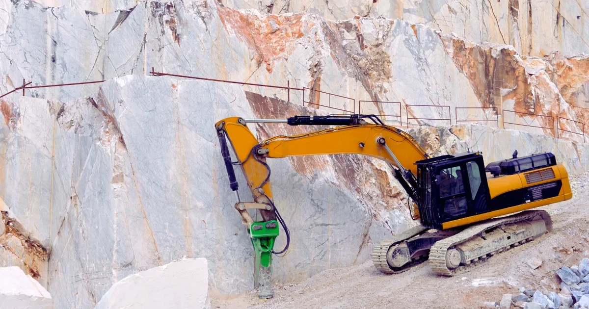
Technical reference image — Liverpool
Local context
Liverpool’s urban expansion from the 18th century onwards meant extensive infilling of docks and river channels with rubble, ash, and colliery spoil. These made-ground zones, particularly around the Baltic Triangle and the former South Docks, create extreme heterogeneity for diaphragm wall construction. We’ve encountered buried timber piles, sandstone blocks, and even cast-iron water mains within the top 8 metres. If the design assumes uniform soil, the trenching rig can hit obstructions that cause bentonite loss, local collapse, and delays. Our approach includes a pre-construction geophysical survey and a staged excavation sequence with contingency for obstructions, ensuring the diaphragm wall design adapts to what’s actually in the ground — not what a historic map suggests.
Full structural design per BS EN 1997 and BS EN 1992-3, including reinforcement schedules, panel layout optimisation, and waterproofing details for permanent walls. We incorporate propping sequences and adjacent structure settlements.
02
Trench Stability and Bentonite Specification
This service complements our laboratory testing work for a complete project analysis.
Relevant standards
BS EN 1997-1:2004 (Eurocode 7) with UK National Annex, CIRIA C760: Guidance on embedded retaining wall design, BS EN 1538:2010 — Execution of special geotechnical works: diaphragm walls, FHWA-RD-97-130: Slurry wall stability analysis
Common questions
Why is diaphragm wall design different in Liverpool compared to other UK cities?
Liverpool’s shallow water table (1.5–3 m depth) and the presence of boulder-rich glacial till mean trench stability is more critical than in stiff clay. The alluvial sands also have high permeability, so bentonite loss and hydraulic fracture risks are elevated. A generic design from a London or Manchester template won’t account for these local conditions.
What is the typical cost range for a diaphragm wall design in Liverpool?
For a typical project in Liverpool, the design fee ranges between £1,470 and £5,200, depending on wall depth, number of panels, and whether temporary or permanent works are included. This covers the desk study, numerical modelling, and structural detailing. Larger schemes with multiple wall types may fall at the upper end.
How do you handle obstructions like old dock walls or buried foundations?
We start with a detailed ground investigation that includes rotary coring through suspected obstructions. The diaphragm wall panel layout is then adjusted to align with known obstructions, and we specify pre-trenching techniques or the use of heavy-duty grabs to break through buried masonry. Contingency panels are included in the design schedule.
What standards do you follow for diaphragm wall design in the UK?
We design strictly to BS EN 1997-1:2004 (Eurocode 7) with UK National Annex, supplemented by CIRIA C760 for embedded retaining walls and BS EN 1538:2010 for execution. For watertightness we apply BS EN 1992-3 crack width limits. All our lab work is UKAS-accredited to ISO 17025.